Robotic Arm (Stage 2)
- Dylan Cecere
- Aug 28, 2023
- 6 min read

Updated: Nov 17, 2024
The design and manufacturing stage can be separated into the following 3 categories:
Electronic Housing
Base & Cycloidal Drive
Final Two Joints
Electronic Housing
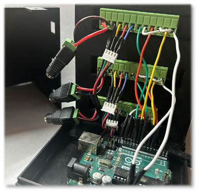
The function of the electrical housing assembly is to store and protect the electronic components for the project which includes the motor drives, developer board, and power distribution connections.
This was my first foray into the 3D printing world and with it came a lot of new and unique challenges. Much troubleshooting was done to get high quality and successful prints before the manufacturing of the parts could begin. Issues such as print bed leveling, temperature optimization, and material selection had all been solved at this point. I decided to use PLA+ for the parts of this project because it was cheap, relatively strong, and widely used and troubleshooted.
The next issue to solve was the tolerancing of the 3D printed parts. The thickness of my FDM printed lines was 0.2mm. The gcode for the print follows the vectors of the CAD surfaces/edges. Thus, the printer has approximately 0.1mm of padding on all surfaces. This becomes an issue when depending on tight tolerances for the parts. Due to this issue, many of the parts required multiple iterations and redesigns. After each print, I measured the actual dimensions of the parts using calipers and adjusted my models by the difference between the printed part and the CAD dimensions.
The next topic explored at this stage in the project was connection/fastening methods. The following methods were used during this project to get experience with each:
Heat Set Inserts with Bolts
Sheet Metal Scew Holes
Rims/Locking Shapes
The following images show the final design and fabricated electrical housing and wiring.


I am proud with the end result developed; however, if I had to change the design of these parts, I would have made the following changes:
Deburring the edges: either using a chamfer or fillet on the sharp edges
Reducing the infill: these housing parts are not structural and thus, the mass can be reduced
Increasing Maintainability: with the current design, the motor drivers cannot be removed unless all electrical connections are disconnected, which can be improved
Using heat shrink tubing for electrical insulation over electrical tape: the electrical tape was unreliable and needed a lot of maintenance. It produces the severe consequence of shorting the components, and thus needs to be mitigated as much as possible
Base and Cycloidal Drive
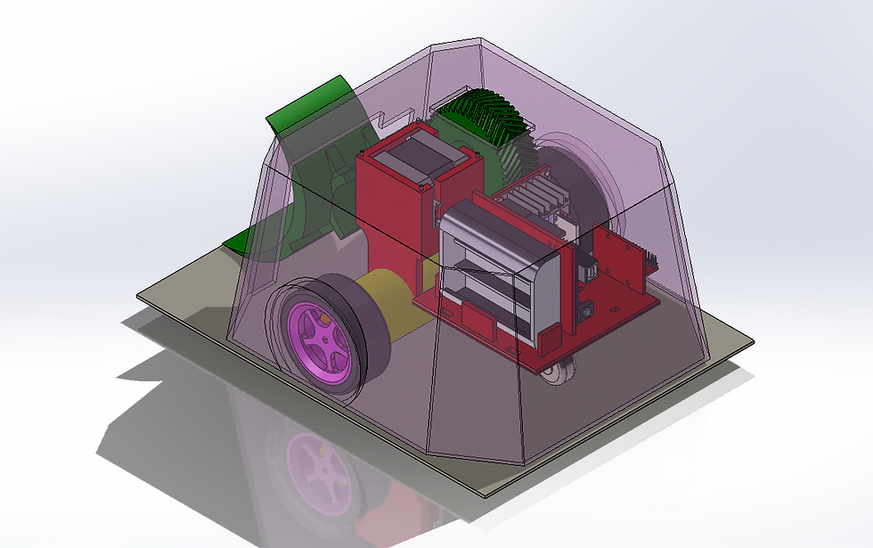
For the base of the robot arm, a cycloidal drive was designed and implemented. This choice was made because I wanted the base to have a wide base and increased inertia to fight against the system's urge to tip when affected by the moment caused by holding weight at a distance from the base. The cycloidal drive had a large diameter cross section and would give me good experience with mechanical design.
A cycloidal drive turns the input shaft’s quick eccentric rotation into slow-powerful concentric rotation in the output shaft. I designed my cycloidal drive to have a 15 : 1 Gear Ratio, but it should be noted that my fabricated cycloidal drive is not 100% efficient due to friction-based energy losses. The base design and cycloidal drive are shown in the images below:


The cycloidal drive uses externally sourced dowels, ball bearings, and fasteners paired with custom 3D printed parts. One of the issues I had during the implementation of this design was purchasing ball bearing and dowels from different manufacturers. When received, the dowels did not fit in the ball bearing bore holes because they were 0.1mm too wide in diameter, thus I had to pivot to using 3D printed bushings instead of ball bearings, which decreased effectiveness. In the future, I would source parts with tighter tolerances.
Some other changes I would make are listed below:
Again, I would debur the edges
I would redesign the feet of the base: the fastening method for these feet is quite awkward. I would make the design more ergonomic, increase the length of the feet to get a wider foundation and eliminate the 90 degree angle between the housing and the feet
Final Two Joints
As discussed in stage 1, after considering the best component choices for my project, I landed on the following choices:
Motor: Nema 17
Main Reasoning: Widely used, easy to precisely control, ability to hold position
Motor Driver: TB6600
Main Reasoning: Widely used, well documented implementation plan
Developer Board: Arduino Uno R3
Main Reasoning: Widely used, well documented, written in a familiar programming language, enough I/O pins
With these components in mind I began to develop a design concept for the robot arm. I researched ways to increase the torque output of my motors to maximize the weight that the arm could hold. Based on the principles of engineering statics, I knew that if I decided on the best motor I could afford with my budget and kept the torque output constant, my options for increasing the load force were as follows:
Cut down weight of robot arm parts
Increase motor torque
- Cycloidal Drives
Decrease the length of the robot limbs

Figure 1. Engineering Statics Problem Simplification
I came to the following conclusions for each of my options:
Changing M is too expensive
Changing L decreases the reach of the robot (undesirable)
Changing the Weight of the parts
Can shift the weight to the left of the motor
Using weight to our advantage
Transfer rotational motion via pulley

Figure 2. Counterweight Design Statics Calculations
Below shows some of the preliminary design concepts to use the 3rd motor as a counterweights and transfer its rotational motion via a pulley system. The challenge here was designing a mechanism to keep the pulley tensioned. I can't have a static design with the pulley tensioned, because then there would be no way to get the pulley into the assembly.


I became busy before being able to finish the design and fabrication of this section yet, but there are many design changes that I would implement here as well. The biggest one being that instead of using rubber bands to hold the tension mechanism for the pulley, I would use something more reliable and simple such as springs. Additionally, I would like to have more thermal cooling for the motors and put a heat sink between the motors and the easily meltable PLA. Additionally, it would have made a lot more sense to implement a motor drive in the second joint rather than the base joint because the second joint is what will be carrying the largest load (and the load of the first joint is very low due to the use of ball bearings to reduce the friction caused by the weight of the upper portion of the robot).
I am still working on the design and fabrication of these parts and will update this post as updates become significant.
Additionally, the controls implementation will be posted here as well. To cover the control software implementation briefly, an inverse kinematic function is used in the program to accept user x,y,z values for the arm to travel to and output the steps that each motor needs to take to get to that position. Additionally, the code is parametric, meaning that as the dimensions of the design (such as limb length) change, only a variable value needs to be updated to fix the controls. An additional consideration is the motion reality versus theory. For instance, the stepper motors have a set number of steps per rotation, thus in theory it should be assumed that each step changes the angle of the robot in that axis by 360 degrees / the number of steps per rotation. However, because there is a load on the stepper and due to some deflection in the limbs, the actual rotation per motor step needs to be adjusted via experimentation. The way I adjusted the values for these steps is by taking a set number of steps with the actual system and measuring the angle change experienced and dividing it by the number of steps the motor took.
Conclusion I am most proud of this project because I was able to learn so many engineering skills and troubleshooting methods:
Learned many technical skills
Exposure to practical problems
Design
Manufacturing
Assembly
Use of engineering principles to guide problem solving
Owned my own learning
Additionally, I was exposed to many other topics that I didn't yet get a chance to explore that can build upon this project in future iterations:
Generative Design
New Filament Materials
User Interface Controls
Part Design Best Practices
Design Analysis and Optimization
Machining


Comments